**[Will's Journal](../index.html)**
(#) **2024/06/07: GPU-Driven Rendering, Frustum Culling**
(###) **GPU-Driven Rendering**
Though only a brief time since the last journal entry, much has changed with my engine. After reading up on how tasks can be offloaded to the GPU for better parallelization, I decided to attempt to design my pipelines
to be GPU-Driven. VkGuide has a chapter on this but it pertained to the older version of the guide, so I decided to make my own implementation. The sample of [GPU Rendering and Multi-Draw Indirect](https://docs.vulkan.org/samples/latest/samples/performance/multi_draw_indirect/README.html) found in
Vulkan's official documentation was helpful as a jumping off point, but much work needed to be done to achieve this task.
This process began with thinking of how to structure the data. After some mental torture, I had decided on the following structure:
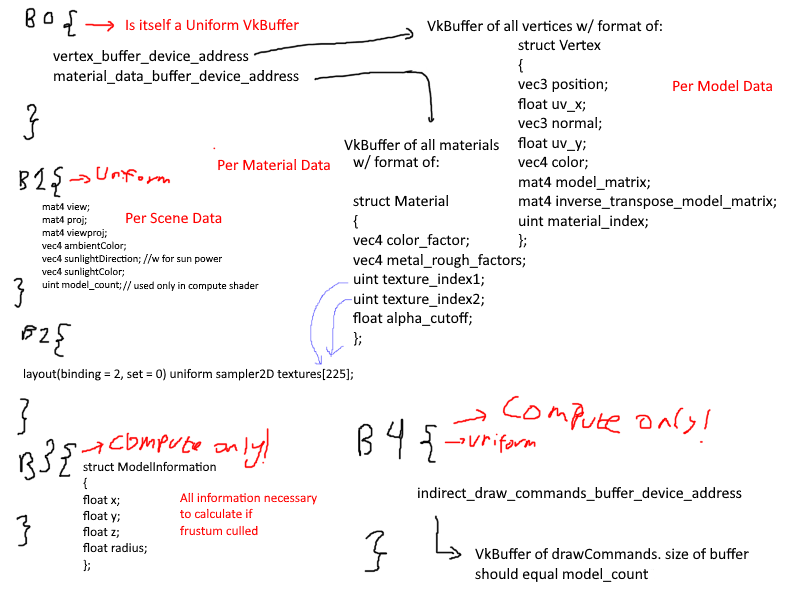
it is slightly messy, but I thought i should have 5 bindings, 3 used by the graphics pipeline and 3 used by the compute pipeline for frustum culling. The first binding would hold the vertex buffer through a buffer device address,
which if you aren't already using it, I highly recommend. Each vertex would hold all data it needed to draw itself: the material index (which would access the array found in the material_data_buffer), the model matrix, etc.
There were a couple of major problems with this that I couldn't accept.
1. Having the model matrix in the vertices ballooned the storage requirements of the vertex buffer.
2. Not seen here is how the data is managed as a whole. In short, each sub-mesh in a model would create a new bunch of vertices in the Vertex data, further increasing storage costs through redundancy.
Having duplicated data is great if you want small changes that may differ for each sub-mesh in the mesh, but in the majority of cases, creating these duplicates only reduces the amount of GPU memory you have to work with.
Not far into working on this implementation, these ideas were scrapped.
A big part of the change to the renderer is how the data is organized in the application. There is a whole new class that constructs the data to be more data-oriented, with almost no class representations of the
objects. Instead, the data is neatly laid out in arrays to be mapped directly into the GPU. This includes: Images (textures), Samplers, and Materials.
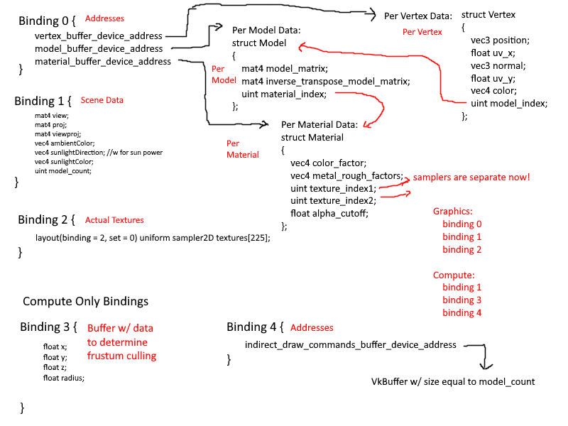
Every time I refactored the data layout, I updated my diagram. This was mostly done to clearly map out my thought process on how the data would flow in the application. I spent a great deal of time considering what kinds of data are associated with
what level of granularity. Frequently I had removed something only to immediately add it back in. It was a mess and I am ashamed it took me as long as it did to come up with a suitable data layout.
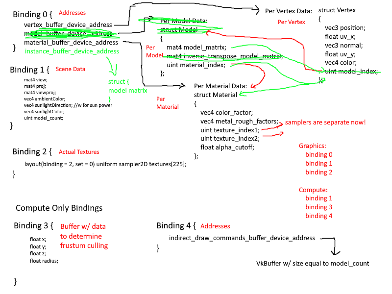
Eventually I had settled on 3 layers of granularity:
- Per Mesh
- Vertices
- Textures
- Samplers
- Per Material
- Base Color
- Metallic/Roughness Factors
- Texture and Sampler Indices
- Per Instance
- Model Matrix
- Vertex Offset and Size (There is some data duplication here, but it is minimal)
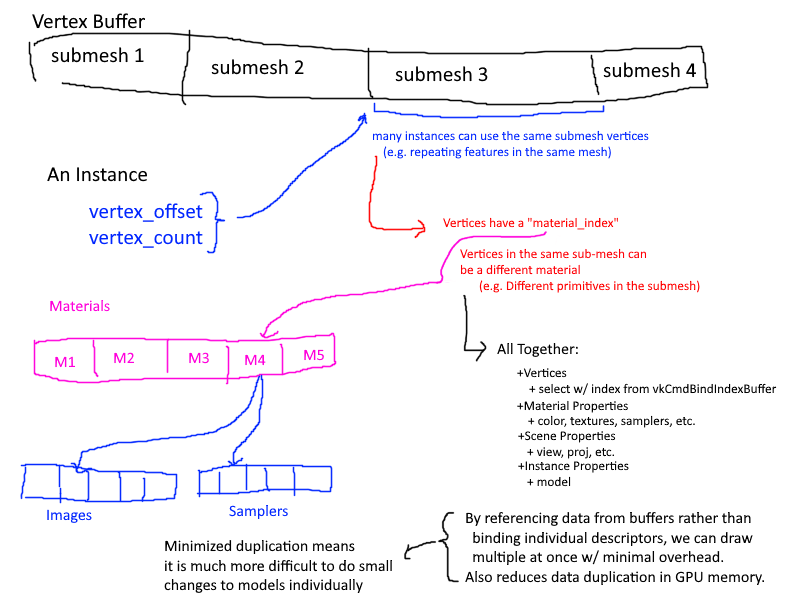
Each Mesh would combine the vertices of all sub-meshes into one large vertex buffer and keep track of the offsets and size of each mesh. Then when an instance is created, as specified by the node-based structure of the gltf file, it would store
this offset and size. Additionally, each vertex would have the following properties:
~~~~~~~~~~~~~~~~~~~~~~~~~~~~~~~~~~~
struct MultiDrawVertex {
glm::vec3 position;
glm::vec3 normal;
glm::vec4 color;
glm::vec2 uv;
uint32_t materialIndex;
};
~~~~~~~~~~~~~~~~~~~~~~~~~~~~~~~~~~~
This is because a sub-mesh is comprised of a set number of primitives, and each primitive can be made of a different material. Thus, when creating the vertex buffer, I also included the material index to reduce the number of levels I had to maintain.
This only came at the cost of 4 bytes per vertex, which isn't too much, especially since it can be packed into the gaps of the 16 byte alignments.
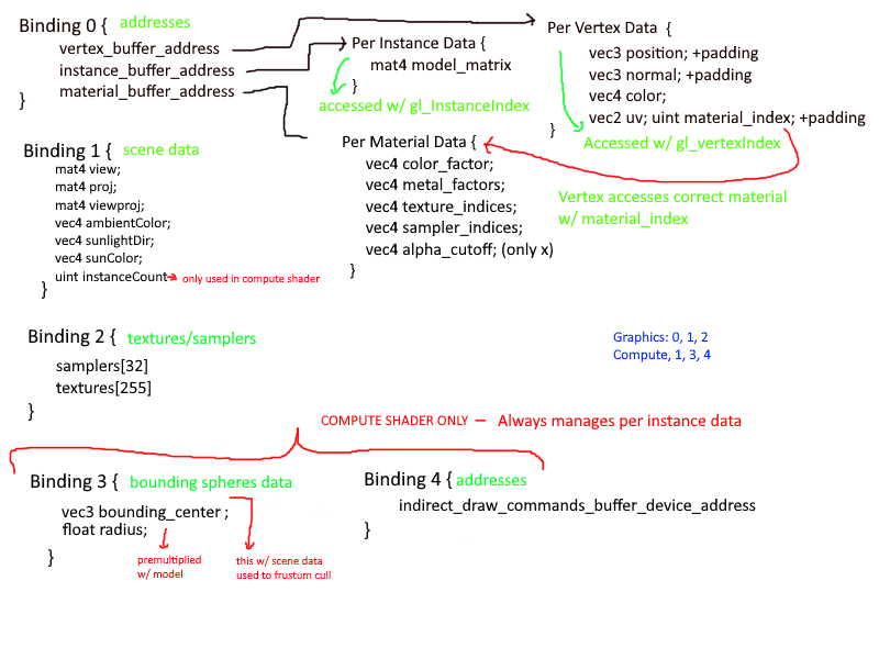
The final structure is as follows:
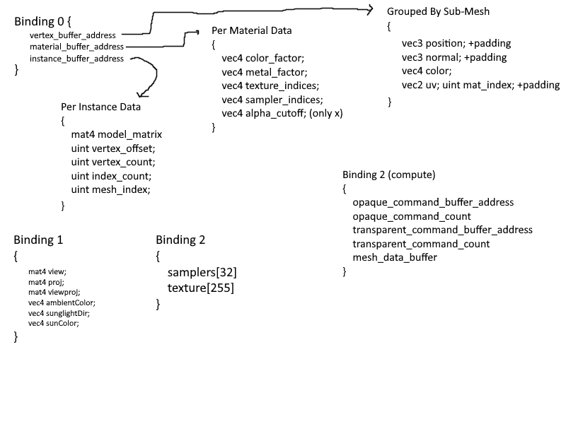
I think it is fairly efficient, clear, and simple solution. Because I store and access vertices through a buffer device address, instead of supplying a vertex offset to the **`VkDrawIndexedIndirectCommand`**, I instead supply it myself through
the per instance data. This solution is not only faster than before, but is also allows for easier incorporation of the GPU for techniques such as Frustum and Occlusion Culling. As for memory, this solution uses equal or slightly less memory than
the old renderer.
My solution leverages the organization of gltf filesa and minimizes data duplication on GPU memory. Taking a step back to look at the bigger picture, my implementation is not much different from VkGuide's solution. Their solution
has shared resources contained in objects on the CPU, whereas mine stores these shared resources in arrays of VkBuffers.
I can safely say that it turned out much better than I could have ever hoped.
(###) **Frustum Culling**
To be honest, the choice to shift to a GPU-Driven renderer actually came about due to my interest in implementing culling. I noticed that there exists a way to do it with the GPU rather than the CPU and thought: GPU goes brrrr.
Frustum culling was easy enough to implement, though my bounding sphere algorithm is shamelessly ripped off from the vulkan sample, and isn't the most efficient algorithm. The compute pipeline was inifinitely easier to set up and get working than the
graphics pipeline, and basically worked upon first iteration, which is unbelievable!
Something that helped me develop the structure faster was working backwards.
Rather than thinking of the data layout, creating the pipeline, then writing the shaders; I instead started with the shaders, then worked on the data layout and finally the pipeline.
The data's purpose is to be finally processed by the shader, so understanding what the data needed to look like; what kind of data the shaders needed to make the necessary calculations, simplified the process greatly.
When looking at a blank scene with 0 meshes in frame (and hopefully their bounding spheres too), my GPU usage drops from a whopping 95% when drawing 9 copies of the "structure" scene to a staggering 0-10%,
which is the GPU doing the "GPU-Driven" calculations.
Whats next? I think I'll be doing some work on a simple shading model to make my scenes look slightly better. I'll also want to do some work on shadows. I did some shadow mapping in the past, but it was extremely brute force and did not scale at all.
I'm planning to tackle cascaded shadow maps for a directional light. Though I am considering potentially looking into deferred rendering, which I have never implemented before. I'll think about it over the next day or so.